Term Project Paper:
Use of Polymers in the development of Electrolytes in Solid State Batteries
Damian Fu Hai Kao
Dr. S S Wang
MECE 5397
December 10 2019
Table of Contents
1. Introduction…………………………………………………………………….…..3
2. Discussion
2.1. Dry Solid Polymer Electrolytes (Dry SPE).............................................................4
2.1.1. Plasticized polymer electrolyte (PPEs)................................................................5
2.1.2. Composite polymer electrolytes (CPEs)..............................................................6
2.2. PVdF-HFP based Polymer Electrolytes……………………………………….…..7
2.3. Poly Ethylene Oxide - Graphene Oxide based Polymer Electrolytes………..…...8
3. Conclusion……………………………………………………………………....….12
4. Documentation……………………………………………………………....……..13
__________________________________________________________________
List of Tables and Figures
Tables:
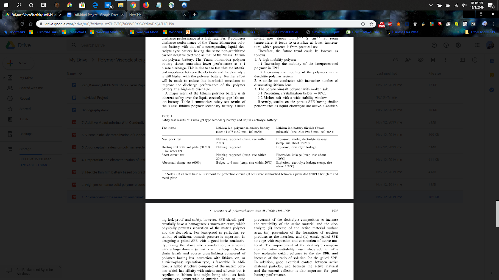
1: Safety test results of Yuusa gel type secondary battery and liquid electrolyte battery [1]
Figures:
1. Chemical Structures of some polar polymers used for polymer electrolytes [5]
2. DSC curves of PVdF-HFP [4]
3. DSC curves of PEO- GO [2]
1. Introduction
Lithium Ion cells have been around for decades. Although its technology has been improved upon over its lifetime, it still has some fundamental issues with regards to its structural composition. This is largely due to it having a liquid based electrolyte, which is prone to many safety issues. Table 1 compares the safety test results between a polymer based cell, and a liquid based cell conducted by Murata[1]. The polymer based cell is significantly safer even when exposed to relatively high temperatures, whereas the liquid based cells are prone to “leakage, solid electrolyte interphase (SEI), dendrite growth, electrical shorting, thermal runaway, and in severe cases, catastrophic hazards.”[2]
One method to tackle this problem is to replace the liquid electrolyte with a dry Solid Polymer Electrolyte (SPE). Given the recent improvements in polymer technology, many groups have begun research on how polymers could be used to create an ideal electrolyte. The goal is to be able to make a flexible solid state battery, and for this reason, not only do energy output and capacity have to be acceptable, but also the mechanical/ structural properties of the polymers in use. They should be able to bend and fold over extended periods of time as the cell undergoes charge and discharge cycles.
For this project, we will first look at the technical benefits of using dry solid polymer electrolytes and its variants. Then, some examples of polymer based electrolytes (specifically, PEO-GO based by Yuan et al.[2] and Kammoun et al.[3], and PVdF-HFP based by Gebreyesus et al.[4]), their method of production as well as testing procedures will be studied.
Table 1: Safety test results of Yuusa gel type secondary battery and liquid electrolyte battery [1]
2. Discussion
2.1. Dry Solid Polymer Electrolytes (Dry SPE)
The main advantages of dry SPEs are good mechanical strength, ease of thin film fabrication with desirable shapes, and the ability of forming good electrode/electrolyte contact [6]. The main drawbacks of SPEs are their high crystallinity and low ionic conductivity [5]. Polymer electrolytes have both crystalline and amorphous regions, and according to Aziz, the ion transport occurs mainly in the amorphous region rather than the crystalline region, but the polymer’s host materials that are used in Polymer Electrolytes are often semi-crystalline [5].
Polymer hosts are chosen for electrolytes based on two factors: the existence of polar (functional) groups with a large power of sufficient electron donor, and allow hindrance to bond rotation [5]. Fig. 1 shows the chemical structures of some important polymers that can be used as host polymers in Polymer Electrolytes.
Plasticizer can be added to improve the SPE’s ambient ionic conductivity. Through using plasticizers, the amorphous region and ion aggregates in PEs can be increased and dissociated, respectively, and thereby improve the DC electrical conductivity of the SPE [7]. According to Murata, the performance of the dry SPE can also be improved by enhancing the mobility of the polymer chains, and by increasing the carrier density [1].

Fig. 1. Chemical Structures of some polar polymers used for polymer electrolytes: (a) Poly (ethylene oxide) (PEO), (b) Poly(vinyl alcohol) (PVA), (c) Poly(methyl methacrylate) (PMMA), (d) Poly( 3-caprolactone) (PCL), (e) Chitosan (CS), (f) Poly(vinylpyrrolidone) (PVP), (g) Poly(vinyl chloride) (PVC), and (h) Poly(vinylidene fluoride) (PVDF). [5]
2.1.1. Plasticized polymer electrolyte (PPEs)
Plasticized Polymer Electrolytes are a branch of PEs that are prepared by incorporating the polymer host with low molecular weight compounds like ethylene carbonate, propylene carbonate and poly ethylene glycol (PEG) [5]. Plasticizers can reduce the number of active centers and weaken the intermolecular forces between the polymer chains [5]. Adding low molecular weight plasticizers decreases the glass transition temperature (Tg) of the PE system, which reduces the crystallinity and enhances the charge carried [5]. According to Pradhan, the crystallinity is reduced when the plasticizer (PEG200) is added to polyethylene oxide (PEO) based nanocomposite polymer electrolytes [7]. In general, adding plasticizer to PEs results in the loss of mechanical strength.
2.1.2. Composite polymer electrolytes (CPEs)
According to Aziz, one of the major reasons behind the poor ionic conductivity of polymer electrolytes has been the presence of ion pairs and triplets, which is a result of the weak dielectric constant of the host polymers [5]. To solve these issues, inorganic inert fillers with high dielectric constant can be dispersed in PEs [5]. Dielectric permittivity can be properly adjusted by controlling the type and the amount of incorporated inorganic filler material. Ceramic materials are classified as inorganic fillers, and are usually fragile and have low dielectric strength [5]. Polymers on the other hand are flexible and easy to process. Therefore, by combining the advantages of these two materials, i.e., ceramic filler and polymer material, new hybrid composite materials with high dielectric constants can be fabricated [5]. According to Yuan et al., incorporating ceramic nanofillers into polymer electrolytes improves ion conductivity without compromising the mechanical properties [2]. “The enhanced properties are attributed to the large surface-to-volume ratio, robust mechanical strength, specific surface chemistry, and interfacial effects of the nanofillers.” [2]
2.2. PVdF-HFP based Polymer Electrolytes
Gebreyesus et al. developed polymer electrolytes composed of poly(vinylidene fluoride-co-hexafluoropropylene) (PVdF-HFP), poly(methyl methacrylate) (PMMA) and lithium triflate (LiTf). One of the reasons behind this choice of PE is that lithium ion conducting PVdF-HFP based blend electrolytes result in enhanced conductivity and mechanical properties [4]. They also have good electrochemical stability and non-combustibility because they have both a crystalline phase and an amorphous phase [4]. “The amorphous phase of PVdF-HFP traps a large amount of liquid electrolyte, which then provides mobile cations more free volume results in enhanced ionic conductivity. The crystalline phase acts as a structural support for the formation of free standing polymer electrolyte film.” [4] Also, PVdF-HFP has a high dielectric constant (ε = 8.4) and low glass transition temperature (Tg). The high dielectric constant facilitates dissociation of salts, giving rise to a high concentration of charge carriers in the electrolyte and thus higher ionic conductivity.
Gebreyesus et al. analyzed the thermal properties of this polymer electrolyte using Differential Scanning Calorimetry (DSC) measurements [4]. Fig. 2 shows the DSC curves of pure PVdF-HFP, pure PMMA, PVdF-HFP:LiTf (75:25 wt.%) and the highest conducting PVdF-HFP:PMMA:LiTf film (BL3).
When the PVdF-HFP:LiTf complex is blended with PMMA, the endothermic peak obtained at 114 °C before blending is observed to re-shift towards a higher temperature of 136 °C.This can be observed from the DSC curve for BL3 in Fig. 2(d). This implies that the thermal stability of the salted PVdF-HFP electrolyte is greatly improved when blended with PMMA. No exothermic peaks were detected for the investigated polymer blend electrolyte, which means that no decomposition takes place up to at least 350 °C. This thermal stability is beneficial especially for battery safety.

Fig. 2. DSC curves of PVdF-HFP, PMMA, PVdF-HFP:LiTf (75:25) and PVdF-HFP:PMMA:LiTf (52.5:22.5:25) complex. [4]
2.3. Poly Ethylene Oxide - Graphene Oxide based Polymer Electrolytes
In their study, Yuan et al. fabricated a solid PEO–LiClO4-GO polymer nanocomposite electrolyte by solution blending and evaporation casting [2]. The resultant composite electrolyte with 1 wt% GO shows an ion conductivity (~10-5 S cm-1) compared to that of pure polymer electrolyte (~10-7 S cm-1). “The enhancement of ion conductivity with the addition of GO fillers can be mainly attributed to the reduced crystallinity and increase in polymer chain mobility as indicated by the lower Tg measurements of the GO filled polymer electrolyte, potential formation of GO ion transport channels, and increase in salt dissociation.” [2] The tensile strength of the polymer composite electrolyte increased by 260% compared to that of pure polymer electrolyte, which can be attributed to the superior mechanical properties of the GO sheets and the strong interaction between the GO and the surrounding PEO host. The Graphene Oxide fillers appear to improve the thermo- mechanical stability of the polymer electrolyte.
The mobility of the polymer chains was investigated by thermal analysis of solid PEO–LiClO4–GO using differential scanning calorimetry (DSC). The DSC curves are shown in Fig 3.The melting point (Tm) and the glass transition temperature (Tg) of the polymer electrolyte lms are shown in Fig. 3a. The crystalline fraction (xc) shown in Fig. 3b is calculated by the following equation:
xc (%) = (ΔHm/H0m) x 100
where, ΔHm is the fusion heat of PEO/Li–xGO (x = 0, 0.5%, 1%, 3%, 5%), and H0m is the melting heat of pure PEO crystalline, 213.7 J g-1 (100% crystalline).[2] The fusion heat (Hm) can be calculated from the integral area of the DSC curves.
Based on the DSC results, the melting temperature and crystallinity of the nanocomposite electrolyte decreases with the addition of GO nanosheets. This means that the crystallization of the PEO chains is disrupted by the presence of GO nanosheets with ultra-large surface area.
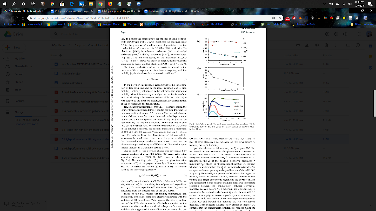
Fig. 3. (a) Melting Point (Tm) and glass transition temperature (Tg) (b) crystalline fraction (xc) and (c) stress - strain curves of polymer electrolyte films. [2]
When lithium salt is added, the Tg of pure PEO film increases from 60 to 20 C. “This phenomenon is referred to as the “salt effect” and is attributed to the formation of complexes between PEO and ClO4.”[2] Upon the addition of GO nanosheets, the Tg of the polymer electrolyte decreases. The presence of GO sheets greatly disturbes the compact molecular packing and crystallization of the solid PEO, leading to the lower Tg values. “In general, a low Tg indicates increase in free volume and larger amorphous regions in the polymer matrix and higher polymer chain mobility. Due to intimate relations between ion conductivity, polymer segmental mobility, free volume and Tg, a maximum ionic conductivity is expected to be realized at the lowest Tg which is at 5 wt% GO content in our polymer nanocomposite system.”[2]
The stress–strain curves for the polymer electrolytes are presented in Fig. 3c. The 1 wt% GO electrolyte film shows an ultimate tensile strength of 1.27 MPa indicating more than 260% improvement in the tensile strength of the pure polymer electrolyte (0.35 MPa). “Stress–strain measurements show a large enhancement of the Young's modulus and of the yield-point stress when passing from filler-free to nanocomposite polymer electrolytes. Here, the active nanocomposite particles serve as both filler and “tie molecules,” thus improving the adhesion between the polymer chains.”[2] The PEO/GO composite membranes at lower GO contents (0.5 and 1 wt%) exhibit excellent tensile strength and % elongation properties.
“Flexible batteries with 1% gra- phene oxide embedded in polyethylene oxide polymer host showed enhanced performance. Considerably high charge–dis- charge capacities with relatively low fading rates over 100 cycles were observed while the cyclic mechanical bending test of the flexible batteries reveal high voltage retention.”[3] As the battery is encapsulated using a simple lamination process, it is economical and scalable. Kammoun et al. states that the laminated flexible LIB offers good electrochemical performance and can function over large ranges of mechanical deformation. This added ability to change shape while under charge and discharge cycles alone gives solid polymer electrolyte based batteries an added safety feature, while also being cost effective.
3. Conclusion
In summary, the solid polymer electrolytes (SPE) can be made significantly more effective with the addition of specific blends or fillers. These can contribute to improve ion conductivity, as well as better mechanical stability. Elementary polymer electrolytes have sub-par characteristics compared to their liquid counterparts, but as the experiments show, they can be developed to become as good or even better than liquid electrolytes. This is an important step as this technology has the ability to make battery technology significantly more safer to use. As the SPEs also allow for bending and flexibility, this makes solid state batteries become much more versatile in where they can be used as well.
4. Documentation
[1] Murata, Kazuo, et al. "An overview of the research and development of solid polymer electrolyte batteries." Electrochimica Acta, vol. 2000, no. 45, 2000.
[2] Yuan, Mengying, et al. "High performance solid polymer electrolyte with graphene oxide nanosheets." RSC Advances, vol. 2014, no. 4, Oct. 2014, pp. 59637-42, doi:10.1039/c4ra07919a.
[3] Kammoun, M, et al. "Flexible thin-film battery based on graphene-oxide embedded in solid polymer electrolyte." Nanoscale, vol. 7, Sept. 2015, pp. 17516-22, doi:10.1039/c5nr04339e.
[4] Gebreyesus, Merhawi A., et al. "Preparation and characterization of lithium ion conducting polymer electrolytes based on a blend of poly(vinylidene fluoride-cohexafluoropropylene) and poly(methyl methacrylate)." Heliyon, vol. 2016, no. 2, 2016, doi:10.1016/j.heliyon.2016.e00134.
[5] Aziz, Shujahadeen B., et al. "A conceptual review on polymer electrolytes and ion transport models." Journal of Science: Advanced Materials and Devices, vol. 3, no. 1, Jan. 2018, pp. 1-17, doi:10.1016/j.jsamd.2018.01.002.
[6] L. Zang, J. Luo, J. Guo, H. Liu, J. Ru, “Preparation and characterization of poly(ethylene glycol)/organo-vermiculite nanocomposite polymer electrolytes.” Polym. Bull. 65 (2010) 669-680.
[7] D.K. Pradhan, R.N.P. Choudhary, B.K. Samantaray, “Studies of dielectric and electrical properties of plasticized polymer nanocomposite electrolytes.” Mater. Chem. Phys. 115 (2009) 557e561.
Comments
Post a Comment